| Common apparatus |
|---|
| Hydraulic system |
| Electronic components |
| Data acquisition |
| EMG monitoring |
| NLID Tools |
| Troubleshooting |
| Materials |
| Supine apparatus |
|---|
| Assembly procedure |
| Safety Measures |
| Components |
| Servovalve |
| Actuator |
| Potentiometer |
| Pressure Filter |
| Torque transducer |
| Boot |
| Literature |
| Computing resources |
|---|
| CVS |
| Ethics |
|---|
| SDS / Inventory |
|---|
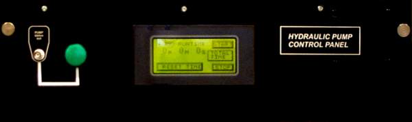
Operator Interface Panel
The hydraulic power unit (HPU) is turned on/off via the operator interface panel shown below. The panel is on all of the time, but the touch sreen will be dark when it enters screen-saver mode.
 This
panel is normally mounted in the instrumentation rack in the lab and connects
to the power box, at the HPU,
via a multi-wire cable running down to the basement. For testing purposes,
the operator interface panel can be relocated next to the HPU and connected
to the power box using a shorter (2.6m) cable, shown here.
This
panel is normally mounted in the instrumentation rack in the lab and connects
to the power box, at the HPU,
via a multi-wire cable running down to the basement. For testing purposes,
the operator interface panel can be relocated next to the HPU and connected
to the power box using a shorter (2.6m) cable, shown here.
Operation
If the LCD touch screen is dark touch it to make it come out of screen-saver mode. PUMP RUNTIME displays the time that the HPU has been running. The virtual buttons on the display do the following:
- START turns on the HPU and starts the PUMP RUNTIME chronometer.
- TOTAL TIME displays the HPU accumulated runtime since this timer was last cleared. (This timer may be cleared in the screen that shows up.)
- STOP turns off the HPU and resets the PUMP RUNTIME chronometer.
- RESET TIME resets the PUMP RUNTIME to 0 while the HPU is running.
A normally open, dry contact, switch is connected to the Pump Status Out BNC. While the HPU is running the switch is closed and the green indicator is lit.
The accumulated runtime meter is used to gage oil maintenance schedule. This timer should only be reset after an oil change. (The runtime is stored in non-volatile memory and is not lost when power is disconnected to the interface panel.)
If the pump is operational and a power failure occurs the pump will not automatically turn on when power is restored.
Warnings (Non-critical)
RUNTIME ABOUT TO EXPIRE
The interface panel has a built-in timer that automatically shuts off the HPU after 4 ½ hours of continuous run time. After the pump runs for 4 hours, a warning window flashes orange indicating RUNTIME ABOUT TO EXPIRE. To reset the timer and extend the runtime the operator has to perform the following steps within 30 minutes of the warning:
- Hit O.K. on the LCD display. (This will bring the display back to the main window.)
- Hit the RESET TIME button.
FILTER re.
FILTER pr.
These warnings are displayed on the main screen and indicate that the return and/or pressure filter(s) on the HPU is(are) blocked. Virtual indicator lights on the screen show which filter is indicating a problem.
Errors (Faults)
Faults are generally indicated by red displays. An example is as follows.
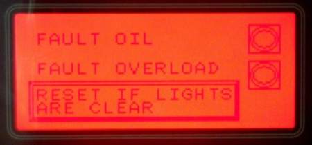
During a fault the pump is shut down and will not be permitted to turn on until the fault is cleared. Faults are latched. Once a fault occurs operator intervention is required to turn the pump back on.
FAULT OIL
FAULT OVERLOAD
Both faults are displayed on the same screen. The active fault is indicated by a blackened circle (indicating a lit error light.)
- FAULT OIL indicates low oil level.
- FAULT OVERLOAD indicates that the electric motor has been overloaded.
When the faults have been resolved hit the RESET IF LIGHTS ARE CLEAR button.
PUMP TOO HOT
This fault indicates that the oil reservoir is too hot. Let the oil cool until the fault light goes off, then hit the RESET IF THE LIGHT IS CLEAR button.
This type of fault should not normally happen. In the event of such a fault investigate its cause.
 Protective
Sheets
Protective
Sheets
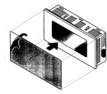
The touch screen is covered with a user-replaceable protective sheet.
Installation instructions (Scan)
Stock is kept in the Bectrol binder.
Components
Panasonic Electric Works of America (formerly Aromat) offers demo applications to program the GT-10 and FP0 modules. Though the applications have imposed limtations they may be still be useful for simple programming requirements.
FPWIN-PRO is used to program the PLC.
GTWIN is used to program the touch screen.
Aromat web site. (Look under Automation Controls section.)
 Aromat
GT-10 Small Touch Screen
Aromat
GT-10 Small Touch Screen
This is the LCD display module. Its function is to report the status of the HPU and to provide the user an interface, via soft keys, to the FP0-C14RS module that controls HPU operation.
Part No: AIGT1000B
Product Summary
Technical Manual (8.21 MB Zip)
This PDF file shows
the display graphical layouts setup by Bectrol.
This ZIP file contains the code that
Bectrol used to program the display.
 Aromat
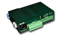
FP0 Series PLC
Aromat
FP0 Series PLC
This is the module that actually controls the HPU. It accepts user input via the touch screen, and HPU status via the various sensors on the unit and acts accordingly.
Part No: FP0-C14RS
Product Summary
Hardware Manual (3.75 MB Zip)
CAD File (Zip)
This
ZIP file contains the PLC program that Bectrol designed for this module.
This PDF file contains
a printout of the PLC prgram ladder. (Scanned from the hard copy that
Bectrol provided.)
For programming, we also have the AFC1520M-US9M interface cable which interfaces the PLC to a computer via an RS232C D-Sub 9-pin port.
Last modified: 2007-01-18 Ross Wagner