| Common apparatus |
|---|
| Hydraulic system |
| Electronic components |
| Data acquisition |
| EMG monitoring |
| NLID Tools |
| Troubleshooting |
| Materials |
| Supine apparatus |
|---|
| Assembly procedure |
| Safety Measures |
| Components |
| Servovalve |
| Actuator |
| Potentiometer |
| Pressure Filter |
| Torque transducer |
| Boot |
| Literature |
| Computing resources |
|---|
| CVS |
| Ethics |
|---|
| SDS / Inventory |
|---|
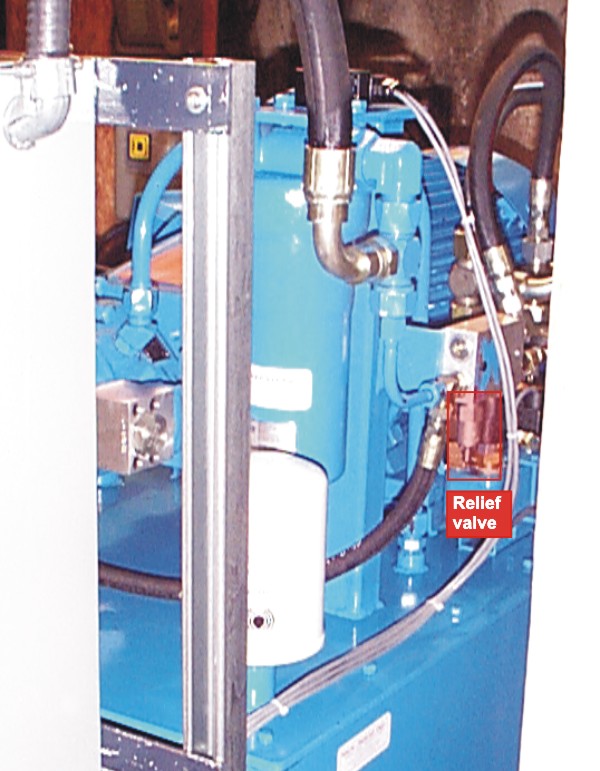
Pump Schematic and Photos
Note: The above schematic diagram is a scan of the diagram provided in the hard copy version of the Operation and Service Manual. It does not include the Asco 8210 normally-closed solenoid, which is in series with thermostatic valve (component #36). The diagram on p. 20 of the electronic version of the Operation and Service Manual does show the solenoid (component #6), but the diagram is harder to read.
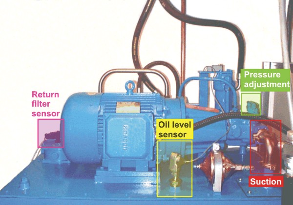
The pump is driven by a 40-HP 1800 RPM electric motor. Power requirements for this unit are: 3-phase, 600 V, 60 Amps.
Hydraulic Power Unit (HPU) Components
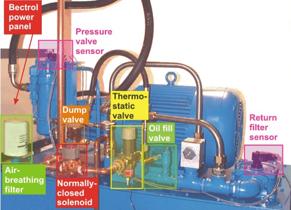
- Dump valve: Function is to depressurize the pressure line. This is a normally open valve and is energized just before the electric motor is powered up.
- Normally-closed solenoid: Opens the water line to cold city water.
- Thermostatic valve: Allows city water to cool the hydraulic fluid returning to the reservoir. The valve is controlled by the temperature of the oil in the reservoir.
- Oil fill valve: The port used to add oil to the reservoir.
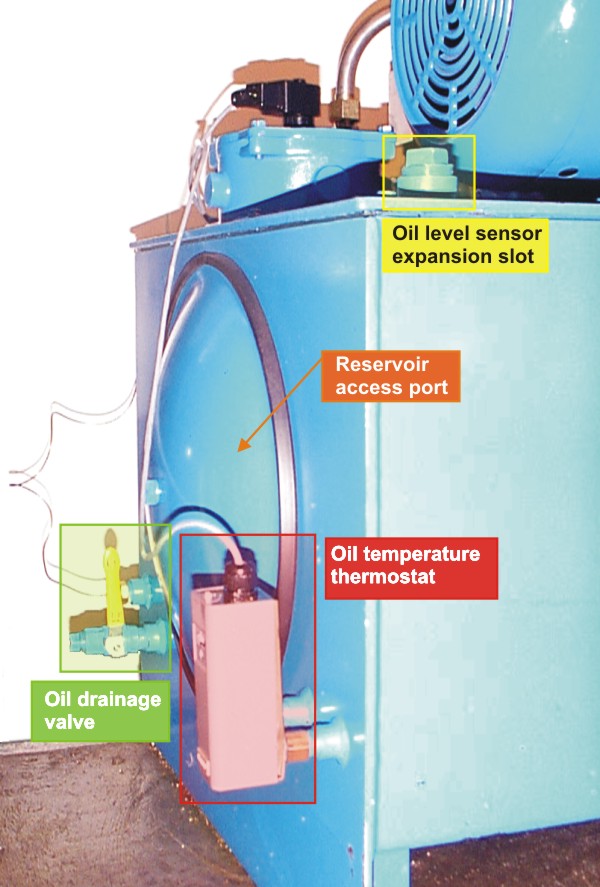
- Oil temperature thermostat: This is a temperature switch that sets the maximum reservoir temperature; it is adjusted to 150 deg F. Should the oil temperature rise above this mark the electric motor will be shutdown.
The choice of 150°F provides a margin of safety since the oil is not cooled when the HPU is off. At elevated temperatures hydraulic oil degrades and can leave a kind of varnish on the system components. At 150°F the oil properties are still okay and the oil may be left to cool by ambient temperature. Under normal operating conditions this temperature level should not be reached anyway.
Last modified: 2006-08-23 Ross Wagner